
Remove Maintenance Station on the Brother GT-541
customer
6-1-7. Replacing the Maintenance Unit
Refer to "6-2-11. Replacing Maintenance PCB" when you replace Maintenance PCB.
Preparation
(1) Make sure GT-541 is not in the middle of any operation.
(2) Press the OK Button on the Control Panel to open the Menu Display.
(3) Press the Up/Down Button to select "Maintenance", and then press the OK Button.

(4) Press the Up/Down Button to select "Cap/Wiper Clean", and then press the OK Button.
(The Platen moves to its storage position, The Cap mechanism of the Maintenance Unit falls off the Print Head Nozzle, and the Carriage moves to the center position and then stops.)
The message "Turn Off & Please Clean Cap & Wiper" appears.
(5) Turn off GT-541, and then unplug the power cord.
(6) Remove the Covers.
(See "7-1. Removing the Covers" for details.)

Removing the Maintenance Unit from the Main Unit
(7) Disconnect the connectors on the PCB in the rear of the Maintenance Unit.

(8) Disconnect the Drain Tube from the Fitting.

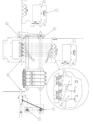
(9) Remove the four bolts (in the red circles shown below) in the front and rear of the Maintenance Unit.

(10) Pull out the Maintenance Unit to the rear.
Installing the Maintenance Unit
(11) Insert the Maintenance Unit from the rear of the Main Unit, and then align the two U-shaped grooves in the front and rear of the Maintenance Unit to the Main Unit Frame positioning pins.

(12) Lightly fasten the four bolts (in the red circles shown below) in the front and rear so that the Maintenance Unit can be moved back and forth.

Adjusting the lengthwise position of the Maintenance Unit
Use the provided MNT Check Gauge shown below for the adjustment.

(13) Rotate the gear of the CL Drive Cam with your finger to move the Print Head Caps to the lower position.

(14) Move the W Rack Gear Unit to the rearmost position with your finger.

(15) Rotate the gear of the CL Drive Cam with your finger to raise the Print Head Caps.

(16) Set the MNT Check Gauge as shown below.

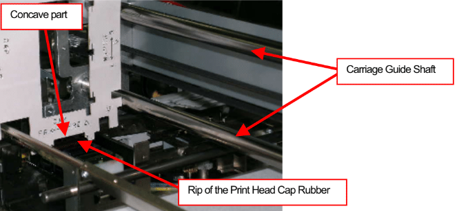
(17) Attach the MNT Check Gauge's reference side to the upper and lower Carriage Guide Shafts, and then confirm that the Rip of the Print Head Cap Rubber is within the Gauge's concave part that shows the allowable range for the lengthwise position (allowable range: +/-0.65 mm).
<Reference>
Adjusting the Maintenance Unit position in the lateral direction (the Print Carriage's scanning direction).
Normally this adjustment is not needed because the position of the Adjusting Board for the Main Base Tray is pre-adjusted with the jig at the factory. When installing or removing the Maintenance Unit from the Main Unit, simply fitting the pins in the slits determines the lateral direction of the Maintenance Unit.

Use the MNT Check Gauge to check the lateral direction of the Maintenance Unit for the arrival check etc. Set the MNT Check Gauge as shown below.
Put the MNT Check Gauge on both the left and right W Guide Shafts, and then set the Gauge at an angle so that the left reference side of the Gauge attaches the Stopper of the Carriage Guide Shaft.

The Gauge's concave parts show the allowable range (+/-1 mm) of lateral position of the Print Head Cap Rubber Rips.
(18) Fasten the four bolts (in the red circles shown below) in the front and rear of the Maintenance Unit securely.

(19) Connect the Drain Tube to the Fitting, and then connect the connectors to the PCB in the rear.

Adjusting or checking the height of the Wiper Blade to the Wiper Guide Shaft
- In case of the unit replacement, this part is pre-adjusted at the factory. If you need to adjust this for some reason, you must remove the Maintenance Unit from the Main Unit because you cannot touch the WL Positioning Cam fixing screw without removing it.
- For the check only, you do not have to remove the Maintenance Unit.
- You can adjust the position of the Wiper Bracket top surface (the height of the Wiper Blade top edge) in relation to the W Guide Shafts by sliding the rear WL Positioning Cam up and down. For this adjustment, use the MNT Check Gauge shown on the next page.


Checking and adjustment by using the MNT Check Gauge
(1) Move the W Rack Gear Unit back and forth by hand so that the position of the WL Trust Shaft to the rear WL Positioning Cam's groove is as shown in the picture below.
<Important>
Make sure that the WL Thrust Shaft is not hung on the slope part of the WL Positioning Cam's groove.
Otherwise, you cannot set the height of the Wiper Blade top edge correctly, because the Wiper Blade will come down.

(2) Set the MNT Check Gauge as shown below to check the height of the Wiper Bracket top surface to the W Guide Shaft top surface. The proper value will be gained when the measuring side edges of the Gauge attach both of them.

To adjust the height of the Wiper Bracket top surface again for replacing parts etc.:
Put the MNT Check Gauge on both left and right W Guide Shafts, and then slide the rear WL Positioning Cam up and down until the Wiper BRacket top surface attaches the Gauge.

Adjusting or checking the height of the Wiper Blade to the Print Heads
You can adjust the height of the Frame FR and the W Guide Shafts hold by the Frame FR by sliding the Frame FR up and down. For this adjustment, use the MNT Check Gauge shown on the next page.

(1) Remove the fixing screw on the top left of the Frame FR, and then move the Wiper Cleaner Detecting Switch to the side temporarily. Otherwise, it will interrupt the setting of the MNT Check Gauge.

(2) Move the Carriage to the Print Head Cap position by hand. (You do not have to disconnect the Print Heads.)
(3) Move the W Rack Gear Unit back and forth by hand so that the position of the WL Thrust Shaft to the rear WL Positioning Cam's groove is as shown in the picture below.
<Important>
Make sure that the WL Thrust Shaft is not hung on the slope part of the WL Positioning Cam's groove.
Otherwise, you cannot set the height of the Wiper Blade top edge correctly, because the Wiper Blade will come down.

(4) Set the MNT Check Gauge in the three steps below.
(This method is for setting the Gauge with the Print Heads Installed.)
(Step 1): Slide the Gauge into the clearance between the Frame FR and the Carriage.
(Step 2): Slide the Gauge to the left along the slit on the lower part until it stops.
(Step 3): Slide the Gauge to the back until it stops.

(5) Push the Frame FR down.
- The MNT Check Gauge shows the correct height of the bottom of the W Guide Shafts on the basis of the Print Head mounting surface (the top surface of the Print Head Holder).
(6) Fasten the four fixing screws on the Frame FR. (See the figure on page 163 for details.)

- The three slits (vertical length: 0.4 mm) on the MNT Check Gauge show the allowable range (+/-0.2 mm) of the tip height of the Wiper Blade behind the Gauge.
Buy Ink and Parts for your Brother GT-541
